Transformerless power supply 30 volts. Transformerless power supplies_1 - Power supplies (transformerless) - Power supplies. power supply option from the charger
Nowadays there is a lot of small-sized equipment in the house that requires constant food. These include watches with LED displays, thermometers, small-sized receivers, etc. In principle, they are designed for batteries, but they run out at the most inopportune moment. A simple way out is to power them from network power supplies. But even a small-sized network (step-down) transformer is quite heavy and takes up quite a bit of space. A pulsed sources Supplies are still complex and require some experience and expensive equipment to manufacture.
A solution to this problem, if certain conditions are met, can be a transformerless power supply with a quenching capacitor. These conditions are...
Full autonomy of the powered device, i.e. no external devices should be connected to it (for example, a tape recorder for recording a program to the receiver); - a dielectric (non-conducting) case and the same control knobs on the power supply itself and the device connected to it.
This is due to the fact that when powered from a transformerless unit, the device is under network potential, and touching its non-insulated elements can “shake” well. It is worth adding that when setting up such power supplies, you should follow safety rules and caution. If necessary, use an oscilloscope for setup, the power supply must be connected via an isolation transformer.
In the very in simple form The circuit of a transformerless power supply has the form shown in Fig. 1.

To limit the inrush current when connecting the unit to the network, resistor R2 is connected in series with capacitor C1 and rectifier bridge VD1, and resistor R1 is connected in parallel to it to discharge the capacitor after disconnection.
Transformerless power supply in general case is a symbiosis of a rectifier and a parametric stabilizer. Capacitor C1 for alternating current is a capacitive (reactive, i.e., not consuming energy) resistance Xc, the value of which is determined by the formula:

where f is the network frequency (50 Hz); C is the capacitance of the capacitor C1, F. Then the output current of the source can be approximately determined as follows:

where Uc is the network voltage (220 V).
The input part of another power supply (Fig. 2a) contains a ballast capacitor C1 and a bridge rectifier consisting of diodes VD1, VD2 and zener diodes VD3, VD4. Resistors R1, R2 play the same role as in the first circuit. The oscillogram of the block's output voltage is shown in Fig. 2b (when the output voltage exceeds the stabilization voltage of the zener diodes, otherwise it works like a regular diode).
From the beginning of the positive half-cycle of the current through capacitor C1 to the moment ti, the zener diode VD3 and diode \U2 are open, and the zener diode VD4 and diode V01 are closed. In the time interval ti...t3, the zener diode VD3 and the diode VD2 remain open, and a stabilization current pulse passes through the opened zener diode VD4. The voltage at the output and at the zener diode VD4 is equal to its stabilization voltage UCT.
The pulse stabilization current, which is through for the diode-zener rectifier, bypasses the RH load, which is connected to the bridge output. At moment t2 the stabilization current reaches a maximum, and at moment 13 it is equal to zero. Until the end of the positive half-cycle, the zener diode VD3 and diode VD2 remain open.
At moment t4 the positive half-cycle ends and the negative half-cycle begins, from the beginning of which to moment ts the zener diode VD4 and diode VD1 are already open, and the zener diode VD3 and diode VD2 are closed. In the time interval ts-.ty, the zener diode VD4 and diode VD1 continue to remain open, and through the zener diode VD3 at voltage UCT a through pulse of stabilization current passes, maximum at the moment te- Starting from 1uid until the end of the negative half-cycle, the zener diode VD4 and diode VD1 remain open. The considered cycle of operation of the diode-stabilizer rectifier is repeated in following periods mains voltage.

Thus, a rectified current passes through the zener diodes VD3, VD4 from the anode to the cathode, and a pulsed stabilization current passes in the opposite direction. In the time intervals t-j...ts and tg.^ty, the stabilization voltage changes by no more than a few percent. The value of the alternating current at the input of the bridge VD1...VD4 is, to a first approximation, equal to the ratio of the network voltage to the capacitance ballast capacitor C1.
The operation of a diode-zener rectifier without a ballast capacitor, which limits the through current, is impossible. IN functionally they are inseparable and form a single whole - a capacitor-zener diode rectifier.
The spread in the UCT values of zener diodes of the same type is approximately 10%, which leads to additional ripples in the output voltage with the frequency of the supply network. The amplitude of the ripple voltage is proportional to the difference in the UCT values of the zener diodes VD3 and VD4.
When using powerful zener diodes D815A...D817G, they can be installed on a common radiator if their type designation contains the letters "PP" (zener diodes D815APP...D817GPP have reverse polarity of the terminals). Otherwise, the diodes and zener diodes must be swapped.
Transformerless power supplies are usually assembled according to the classical scheme: quenching capacitor, rectifier AC voltage, filter capacitor, stabilizer. A capacitive filter smoothes out output voltage ripples. The greater the capacitance of the filter capacitors, the less ripple and, accordingly, the greater the constant component of the output voltage. However, in some cases you can do without a filter, which is often the most cumbersome component of such a power source.
It is known that a capacitor connected to an alternating current circuit shifts its phase by 90°. A phase-shifting capacitor is used, for example, when connecting a three-phase motor to a single-phase network. If you use a phase-shifting capacitor in the rectifier, which ensures mutual overlap of half-waves of the rectified voltage, in many cases you can do without a bulky capacitive filter or significantly reduce its capacitance. The circuit of such a stabilized rectifier is shown in Fig. 3.

The three-phase rectifier VD1 ... VD6 is connected to an alternating voltage source through active (resistor R1) and capacitive (capacitor C1) resistances.
Such a rectifier can be used where it is necessary to reduce the dimensions of an electronic device, since the dimensions of the oxide capacitors of a capacitive filter are, as a rule, much larger than those of a relatively small phase-shifting capacitor.
Another advantage of the proposed option is that the current consumption is almost constant (in the case of a constant load), whereas in rectifiers with a capacitive filter, at the moment of switching on, the starting current significantly exceeds the steady-state value (due to the charge of the filter capacitors), which in some cases is extremely undesirable .
The described device can also be used with series voltage stabilizers that have a constant load, as well as with a load that does not require voltage stabilization.
A completely simple transformerless power supply (Fig. 4) can be built “on the knee” in literally half an hour. In this embodiment, the circuit is designed for an output voltage of 6.8 V and a current of 300 mA. The voltage can be changed by replacing the zener diode VD4 and, if necessary, VD3. And by installing transistors on radiators, you can increase the load current. Diode bridge - any, designed for reverse voltage not less than 400 V. By the way, you can remember about the “ancient” D226B diodes.

In another transformerless source (Fig. 5), the KR142EN8 microcircuit is used as a stabilizer. Its output voltage is 12 V. If adjustment of the output voltage is necessary, then pin 2 of the DA1 microcircuit is connected to the common wire through a variable resistor, for example, type SPO-1 (with linear characteristic changes in resistance). Then the output voltage can vary in the range of 12...22 V.
As a DA1 microcircuit, to obtain other output voltages, you need to use the appropriate integrated stabilizers, for example, KR142EN5, KR1212EN5, KR1157EN5A, etc. Capacitor C1 must be for an operating voltage of at least 300 V, brand K76-3, K73-17 or similar (non-polar , high voltage). Oxide capacitor C2 acts as a power supply filter and smoothes out voltage ripples. Capacitor SZ reduces interference high frequency. Resistors R1, R2 are MLT-0.25 type. Diodes VD1...VD4 can be replaced with KD105B...KD105G, KD103A, B, KD202E. Zener diode VD5 with a stabilization voltage of 22...27 V protects the microcircuit from voltage surges when the source is turned on.
Despite the fact that, theoretically, capacitors in an alternating current circuit do not consume any power, in reality, due to the presence of losses, a certain amount of heat may be released in them. You can check the suitability of a capacitor as a damping capacitor for use in a transformerless source by simply connecting it to the mains and assessing the temperature of the case after half an hour. If the capacitor manages to warm up noticeably, it is not suitable. Special capacitors for industrial electrical installations practically do not heat up (they are designed for high reactive power). Such capacitors are usually used in fluorescent lamps, in starters and control devices of asynchronous electric motors, etc.

In a 5-volt source (Fig. 6) with a load current of up to 0.3 A, a capacitor voltage divider is used. It consists of a paper capacitor C1 and two oxide capacitors C2 and SZ, forming the lower (according to the circuit) non-polar arm with a capacity of 100 μF (counter-series connection of capacitors). The polarizing diodes for the oxide pair are bridge diodes. With the indicated ratings of the elements, the short circuit current at the output of the power supply is 600 mA, the voltage on capacitor C4 in the absence of load is 27 V.

The power supply unit for the portable receiver (Fig. 7) easily fits into its battery compartment. The diode bridge VD1 is designed for operating current, its maximum voltage is determined by the voltage provided by the zener diode VD2. Elements R3, VD2, VT1 form an analogue of a powerful zener diode. The maximum current and power dissipation of such a zener diode are determined by transistor VT1. It may require a heatsink. But in any case, the maximum current of this transistor should not be less than the load current. Elements R4, VD3 - presence indication circuit
output voltage. At low load currents, it is necessary to take into account the current consumed by this circuit. Resistor R5 loads the power circuit with a low current, which stabilizes its operation.

Quenching capacitors C1 and C2 are KBG type or similar. You can also use K73-17 with an operating voltage of 400 V (250 V is also suitable, since they are connected in series). The output voltage depends on the resistance of the quenching capacitors to alternating current, the actual load current and the stabilization voltage of the zener diode.
To stabilize the voltage of a transformerless power supply with a quenching capacitor, you can use symmetrical dinistors (Fig. 8).

When the filter capacitor C2 is charged to the opening voltage of the dinistor VS1, it turns on and bypasses the input of the diode bridge. The load at this time receives power from capacitor C2. At the beginning of the next half-cycle, C2 is recharged to the same voltage, and the process is repeated. The initial discharge voltage of capacitor C2 does not depend on the load current and network voltage, therefore the stability of the unit’s output voltage is quite high. The voltage drop across the dinistor when turned on is small, the power dissipation, and therefore its heating, is significantly less than that of a zener diode. The maximum current through the dinistor is about 60 mA. If this value is not enough to obtain the required output current, you can “power up” the dinistor with a triac or thyristor (Fig. 9). The disadvantage of such power supplies is the limited choice of output voltages, determined by the switching voltages of the dinistors.
It is more profitable and easier to power low-voltage electrical and radio equipment from the mains. Transformer power supplies are most suitable for this, since they are safe to use. However, interest in transformerless power supplies (BTBP) with stabilized output voltage does not wane. One of the reasons is the complexity of manufacturing the transformer. But for the BTBP it is not needed - only the correct calculation is required, but this is precisely what scares inexperienced novice electricians. This article will help you make calculations and facilitate the design of a transformerless power supply.
A simplified diagram of the BPTP is shown in Fig. 1. Diode bridge VD1 is connected to the network through a quenching capacitor C gas, connected in series with one of the diagonals of the bridge. The other diagonal of the bridge works for the load of the block - resistor R n. A filter capacitor C f and a zener diode VD2 are connected in parallel to the load.
The calculation of the power supply begins with setting the voltage U n on the load and the current strength I n. consumed by the load. The greater the capacitance of the capacitor C, the higher the energy capabilities of the BPTP.
Capacitance calculation
The table shows data on the capacitance X c of the capacitor C gas at a frequency of 50 Hz and the average value of the current I cf passed by the capacitor C gas, calculated for the case when R n = 0, that is, when short circuit loads. (After all, the BTBP is not sensitive to this abnormal operating mode, and this is another huge advantage over transformer power supplies.)Other meanings capacitance X s (in kilo-ohms) and the average current value I sr (in milliamps) can be calculated using the formulas:
C extinguisher is the capacitance of the quenching capacitor in microfarads.
If we exclude the zener diode VD2, then the voltage U n on the load and the current I n through it will depend on the load R n. It is easy to calculate these parameters using the formulas:

U n - in volts, R n and X n - in kilo-ohms, I n - in milliamperes, C gas - in microfarads. (The formulas below use the same units of measurement.)
As the load resistance decreases, the voltage on it also decreases, and according to a nonlinear dependence. But the current passing through the load increases, although very slightly. So, for example, a decrease in R n from 1 to 0.1 kOhm (exactly 10 times) leads to the fact that U n decreases by 9.53 times, and the current through the load increases by only 1.05 times. This “automatic” current stabilization distinguishes BTBP from transformer power supplies.
Power Рн at the load, calculated by the formula:

with a decrease in Rn, it decreases almost as intensely as Un. For the same example, the power consumed by the load is reduced by 9.1 times.
Since the current I n of the load at relatively small values of resistance R n and voltage U n on it changes extremely little, in practice it is quite acceptable to use approximate formulas:

By restoring the zener diode VD2, we obtain stabilization of the voltage U n at the level of U st - a value that is practically constant for each specific zener diode. And with a small load (high resistance R n), the equality U n = U st.
Load resistance calculation
To what extent can R n be reduced so that the equality U n = U st is valid? As long as the inequality holds:
Consequently, if the load resistance turns out to be less than the calculated Rn, the voltage on the load will no longer be equal to the stabilization voltage, but will be somewhat less, since the current through the zener diode VD2 will stop.

Calculation of permissible current through a zener diode
Now let’s determine what current I n will flow through the load R n and what current will flow through the zener diode VD2. It is clear that
As the load resistance decreases, the power consumed by it P n =I n U n =U 2 st /R n increases. But the average power consumed by the BPTP is equal to

remains unchanged. This is explained by the fact that the current I cf branches into two - I n and I st - and, depending on the load resistance, is redistributed between R n and the zener diode VD2, and so that the lower the load resistance R n, the less current flows through Zener diode, and vice versa. This means that if the load is small (or completely absent), the zener diode VD2 will be in the most difficult conditions. That is why it is not recommended to remove the load from the BPTP, otherwise all the current will go through the zener diode, which can lead to its failure.
The amplitude value of the network voltage is 220·√2=311(V). The pulse value of the current in the circuit, if we neglect the capacitor C f, can reach

Accordingly, the zener diode VD2 must reliably withstand this pulse current in case of accidental disconnection of the load. We should not forget about possible voltage overloads in the lighting network, amounting to 20...25% of the nominal value, and calculate the current passing through the zener diode when the load is off, taking into account a correction factor of 1.2...1.25.
If there is no powerful zener diode
When there is no zener diode of suitable power, it can be fully replaced with a diode-transistor analogue. But then the BTBP should be built according to the scheme shown in Fig. 2. Here the current flowing through the zener diode VD2 decreases in proportion to the static base current transfer coefficient powerful n-p-n transistor VT1. The voltage of the UCT analogue will be approximately 0.7V higher than Ust of the lowest-power zener diode VD2 if the transistor VT1 is silicon, or by 0.3V if it is germanium.A transistor is also applicable here. p-n-p structures. However, then the circuit shown in Fig. is used. 3.
Half-wave block calculation
Along with a full-wave rectifier, the simplest half-wave rectifier is sometimes used in BTBP (Fig. 4). In this case, its load Rn is powered only by positive half-cycles of alternating current, and the negative ones pass through the diode VD3, bypassing the load. Therefore, the average current I cf through diode VD1 will be half as much. This means that when calculating the block, instead of X c, you should take 2 times the resistance equal to![]()
and the average current with a short-circuited load will be equal to 9.9 πС extinguisher = 31.1 С extinguishing. Further calculation of this version of the BPTP is carried out completely similarly to the previous cases.
Calculation of voltage on the quenching capacitor
It is generally accepted that with a network voltage of 220V, the rated voltage of the quenching capacitor C should be at least 400V, that is, with approximately a 30 percent margin in relation to the amplitude network voltage, since 1.3·311=404(V). However, in some of the most critical cases, its rated voltage should be 500 or even 600V.And further. When selecting a suitable capacitor C, it should be taken into account that it is impossible to use capacitors of the types MBM, MBPO, MBGP, MBGTs-1, MBGTs-2 in BTBP, since they are not designed to operate in alternating current circuits with an amplitude voltage value exceeding 150V.
Capacitors MBGCh-1, MBGCh-2 with a rated voltage of 500V work most reliably in BTBP (from old washing machines, fluorescent lamps, etc.) or KBG-MN, KBG-MP, but for a rated voltage of 1000V.
Filter capacitor
The capacitance of the filter capacitor C f is difficult to calculate analytically. Therefore, it is selected experimentally. Approximately, it should be assumed that for each milliamp of average current consumed, it is required to take at least 3...10 μF of this capacitance if the BTBP rectifier is full-wave, or 10...30 μF if it is half-wave.The rated voltage of the oxide capacitor used C f must be at least U st And if there is no zener diode in the BTBP, and the load is constantly on, the rated voltage of the filter capacitor must exceed the value:
If the load cannot be turned on constantly and there is no zener diode, the rated voltage of the filter capacitor should be more than 450V, which is hardly acceptable due to large sizes capacitor C f. By the way, in this case the load should be reconnected only after disconnecting the BTBP from the network.
And that is not all
It is advisable to supplement any of the possible BTBP options with two more auxiliary resistors. One of them, the resistance of which can be in the range of 300 kOhm...1 MOhm, is connected in parallel with the capacitor C extinguisher. This resistor is needed to speed up the discharge of capacitor C after disconnecting the device from the network. The other - ballast - with a resistance of 10...51 Ohms is connected to the break of one of the network wires, for example, in series with the capacitor C extinguisher. This resistor will limit the current through the diodes of the VD1 bridge when the BTBP is connected to the network. The dissipation power of both resistors must be at least 0.5 W, which is necessary to guarantee against possible surface breakdowns of these resistors high voltage. Due to the ballast resistor, the zener diode will be loaded somewhat less, but the average power consumed by the BTBP will increase noticeably.What diodes to take
The function of the full-wave rectifier BTBP according to the circuits in Fig. 1...3 can be made by diode assemblies of the KTs405 or KTs402 series with letter indices Ж or И, if the average current does not exceed 600 mA, or with indices A, B, if the current value reaches 1 A. Four separate diodes connected according to bridge circuit, for example, KD105 series with indices B, V or G, D226 B or V - up to 300 mA, KD209 A, B or V - up to 500...700 mA, KD226 V, G or D - up to 1.7 A .Diodes VD1 and VD3 in the BTBP according to the diagram in Fig. 4 can be any of the above. It is also permissible to use two diode assemblies KD205K V, G or D for a current of up to 300 mA or KD205 A, V, Zh or I - up to 500 mA.
And one last thing. The transformerless power supply, as well as the equipment connected to it, are connected directly to the AC network! Therefore, they must be reliably insulated from the outside, say, placed in a plastic case. In addition, it is strictly forbidden to “ground” any of their terminals, as well as to open the case when the device is turned on.
The proposed methodology for calculating BPTP has been tested by the author in practice for a number of years. The entire calculation is carried out based on the fact that the BPTP is essentially a parametric voltage stabilizer, in which the role of a current limiter is performed by a quenching capacitor.
Magazine "SAM" No. 5, 1998
Transformerless power supplies with a quenching capacitor are convenient in their simplicity, have small dimensions and weight, but are not always applicable due to the galvanic connection of the output circuit with a 220 V network.
In a transformerless power supply, a series-connected capacitor and load are connected to an alternating voltage network. A non-polar capacitor connected to an AC circuit behaves like a resistance, but unlike a resistor, it does not dissipate the absorbed power as heat.
To calculate the capacity of the quenching capacitor, the following formula is used:

C is the capacitance of the ballast capacitor (F); Ieff - effective load current; f is the frequency of the input voltage Uc (Hz); Uc — input voltage (V); Un—load voltage (V).
For ease of calculations, you can use an online calculator
The design of transformerless sources and devices powered from them must exclude the possibility of touching any conductors during operation. Special attention attention should be paid to insulating the controls.
- Similar articles
- - The use of operational amplifiers (op-amps) in portable equipment immediately poses the problem of how to power them with a bipolar voltage of +15 V. A similar question arises because in the reference materials the parameters of most op-amps are given specifically for these supply voltages, and many...
- - Due to the need to ensure electrical strength, the dimensions and weight of high-voltage transformers become very large. Therefore, it is more convenient to use voltage multipliers in high-voltage low-power power supplies. Voltage multipliers are created on the basis of rectification circuits with capacitive...
- - The receiver can be tuned in the range of 70...150 MHz without changing the values of the tuning elements. The real sensitivity of the receiver is about 0.3 µV, the supply voltage is 9 V. It should be noted that the supply voltage of the MC3362 is 2...7 V, and the MC34119 is 2...12 V, so the MC3362 is powered through...
- - To calculate a stabilizer, as a rule, only two parameters are used - Ust (stabilization voltage), Ist (stabilization current), provided that the load current is equal to or less than the stabilization current. For a simple calculation of the stabilizer, we will use the following parameters as an example: Input...
- - The receiver is designed to receive signals in the DV range (150 kHz...300 kHz). main feature receiver in an antenna that has greater inductance than a conventional magnetic antenna. This makes it possible to use the capacitance of the tuning capacitor in the range of 4...20pF, and also such a receiver has...
Somehow recently I came across a diagram on the Internet that was very simple block power supply with voltage regulation. The voltage could be adjusted from 1 Volt to 36 Volt, depending on the output voltage on the secondary winding of the transformer.
Take a close look at the LM317T in the circuit itself! The third leg (3) of the microcircuit is connected to capacitor C1, that is, the third leg is INPUT, and the second leg (2) is connected to capacitor C2 and a 200 Ohm resistor and is an OUTPUT.
Using a transformer, from a mains voltage of 220 Volts we get 25 Volts, no more. Less is possible, no more. Then we straighten the whole thing with a diode bridge and smooth out the ripples using capacitor C1. All this is described in detail in the article on how to obtain constant voltage from alternating voltage. And here is our most important trump card in the power supply - this is a highly stable voltage regulator chip LM317T. At the time of writing, the price of this chip was around 14 rubles. Even cheaper than a loaf white bread.
Description of the chip
LM317T is a voltage regulator. If the transformer produces up to 27-28 volts on the secondary winding, then we can easily regulate the voltage from 1.2 to 37 volts, but I would not raise the bar to more than 25 volts at the transformer output.
The microcircuit can be executed in the TO-220 package:

or in D2 Pack housing

It can pass a maximum current of 1.5 Amps, which is enough to power your electronic gadgets without voltage drop. That is, we can output a voltage of 36 Volts with a current load of up to 1.5 Amps, and at the same time our microcircuit will still output 36 Volts - this, of course, is ideal. In reality, fractions of volts will drop, which is not very critical. With a large current in the load, it is more advisable to install this microcircuit on a radiator.
In order to assemble the circuit, we also need a variable resistor of 6.8 Kilo-Ohms, or even 10 Kilo-Ohms, as well as a constant resistor of 200 Ohms, preferably from 1 Watt. Well, we put a 100 µF capacitor at the output. Absolutely simple scheme!
Assembly in hardware
Previously, I had a very bad power supply with transistors. I thought, why not remake it? Here is the result ;-)

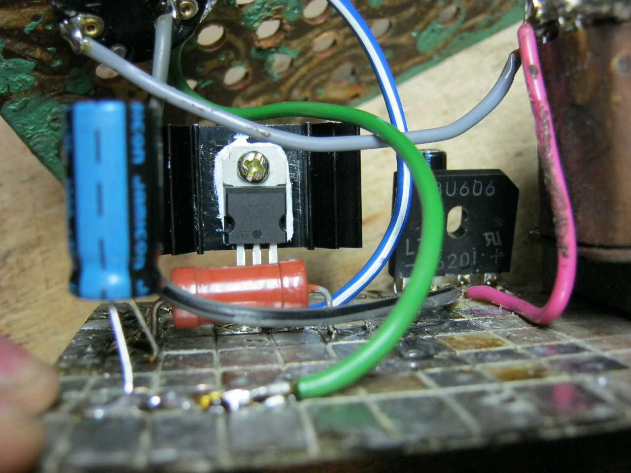
Here we see the imported GBU606 diode bridge. It is designed for a current of up to 6 Amps, which is more than enough for our power supply, since it will deliver a maximum of 1.5 Amps to the load. I installed the LM on the radiator using KPT-8 paste to improve heat transfer. Well, everything else, I think, is familiar to you.
And here is an antediluvian transformer that gives me a voltage of 12 volts on the secondary winding.

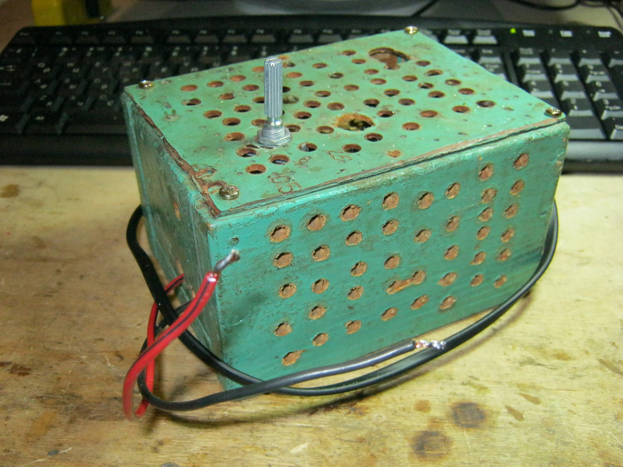
We carefully pack all this into the case and remove the wires.

So what do you think? ;-)
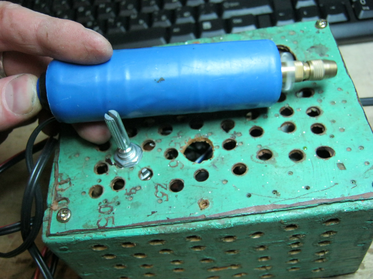
The minimum voltage I got was 1.25 Volts, and the maximum was 15 Volts.


I set any voltage, in this case the most common are 12 Volts and 5 Volts


Everything works great!
This power supply is very convenient for adjusting the speed of a mini drill, which is used for drilling circuit boards.
Analogues on Aliexpress
By the way, on Ali you can immediately find a ready-made set of this block without a transformer.

Too lazy to collect? You can buy a ready-made 5 Amp for less than $2:

You can view it at this link.
If 5 Amps is not enough, then you can look at 8 Amps. It will be enough for even the most seasoned electronics engineer:

They often started asking me how to connect a microcontroller or what low voltage circuit directly to 220 without using a transformer. The desire is quite obvious - a transformer, even a pulse one, is very bulky. And cramming it, for example, into a control circuit for a chandelier located directly in a switch will not work, no matter how much you want. Maybe just hollow out a niche in the wall, but that’s not our method!
Nevertheless, there is a simple and very compact solution - this is a divider on a capacitor.
True, capacitor power supplies do not have isolation from the network, so if something suddenly burns out in it, or goes wrong, then it can easily electrocute you, or burn down your apartment, or even ruin your computer, this is generally a nice thing, in general technique Security here must be respected more than ever - it is described at the end of the article. In general, if I haven’t convinced you that transformerless power supplies are evil, then I’m my own evil Pinocchio, I have nothing to do with it. Okay, closer to the topic.
Remember the usual resistive divider?
It would seem that what the problem is, I chose the required ratings and got the required voltage. Then I straightened Profit. But not everything is so simple - such a divider can and will be able to provide the required voltage, but it will not provide the required current at all. Because resistance is very high. And if the resistances are proportionally reduced, then a large current will flow through them, which at a voltage of 220 volts will give very large heat losses - the resistors will heat up like a stove and eventually either fail or start a fire.
Everything changes if one of the resistors is replaced with a capacitor. The point is - as you remember from the article about capacitors, the voltage and current on the capacitor are not in phase. Those. when the voltage is at its maximum, the current is at its minimum, and vice versa.
Since our voltage is variable, the capacitor will constantly discharge and charge, and the peculiarity of the discharge-charge of a capacitor is that when it has a maximum current (at the moment of charging), then the minimum voltage and vice versa. When it is already charged and the voltage on it is maximum, the current is zero. Accordingly, in this situation, the heat loss power generated by the capacitor (P=U*I) will be minimal. Those. he won't even break a sweat. And the reactive resistance of the capacitor is Xc=-1/(2pi*f*C).
Theoretical retreat
There are three types of resistance in a circuit:
Active - resistor (R)
Reactive - capacitor (X s) and coil (X L)
The total resistance of the circuit (impedance) Z=(R 2 +(X L +X s) 2) 1/2
Active resistance is always constant, and reactive resistance depends on frequency.
X L =2pi*f * L
Xc=-1/(2pi*f*C)
The sign of an element's reactance indicates its character. Those. if it is greater than zero, then these are inductive properties, if less than zero, then they are capacitive. It follows from this that inductance can be compensated by capacitance and vice versa.
f is the current frequency.
Accordingly, at direct current at f = 0 and X L of the coil becomes equal to 0 and the coil turns into an ordinary piece of wire with only one active resistance, and Xc of the capacitor goes to infinity, turning it into a break.
It turns out that we have this diagram:
That's it, current flows in one direction through one diode, in the other through the second. As a result, on the right side of the circuit we no longer have an alternating current, but a pulsating current - one half-wave of a sinusoid.
Let's add a smoothing capacitor to make the voltage calmer, microfarad by 100 and volts by 25, electrolyte:
In principle, it’s already ready, the only thing is that you need to install the zener diode at such a current that it does not die when there is no load at all, because then it will have to take the rap for everyone, pulling through all the current that the power supply can provide.
And you can help him with some help. Install a current-limiting resistor. True, this will greatly reduce the load capacity of the power supply, but this is enough for us.
 |
The current that this circuit can deliver can be roughly calculated using the formula:
I = 2F * C (1.41U - Uout/2).
- F is the frequency of the supply network. We have 50Hz.
- C - capacity
- U - voltage in the socket
- Uout - output voltage
The formula itself is derived from terrible integrals of the shape of current and voltage. In principle, you can google it yourself using the keyword “quenching capacitor calculation”, there is plenty of material.
In our case, it turns out that I = 100 * 0.46E-6 (1.41*U - Uout/2) = 15mA
It’s not extravaganza, but it’s more than enough for MK+TSOP+optointerface to work. And more is usually not required.
Add a couple of condensers for additional power filtering and you can use:
After which, as usual, I etched and soldered everything:
 |
 |
The scheme has been tested many times and works. I once shoved it into the thermal glass heating control system. There was space the size of a matchbox, and safety was guaranteed by the total glassing of the entire block.
SAFETY
In this scheme there is no voltage isolation from the supply circuit, which means the circuit VERY DANGEROUS in terms of electrical safety.
Therefore, it is necessary to take an extremely responsible approach to its installation and selection of components. And also handle it carefully and very carefully when setting up.
First, notice that one of the pins goes to GND directly from the socket. This means that there may be a phase there, depending on how the plug is inserted into the socket.
Therefore, strictly follow a number of rules:
- 1. The ratings must be set with a margin for as high a voltage as possible. This is especially true for the capacitor. I have a 400 volt one, but this is the one that was available. It would be better if it was 600 volts, because... In the electrical network, sometimes there are voltage surges much higher than the nominal value. Standard power supplies, due to their inertia, will easily survive it, but the capacitor can break through - imagine the consequences for yourself. It's good if there is no fire.
- 2. This circuit must be carefully isolated from the environment. Reliable case so that nothing sticks out. If the circuit is mounted on a wall, it should not touch the walls. In general, we pack the whole thing tightly in plastic, vitrify it and bury it at a depth of 20 meters. :)))))
- 3. When setting up, do not touch any of the chain elements with your hands. Don’t let the fact that there is 5 volts at the output reassure you. Since five volts there are exclusively relative to itself. But in relation to environment there are still the same 220.
- 4. After disconnecting, it is highly advisable to discharge the quenching capacitor. Because there remains a charge of 100-200 volts in it, and if you carelessly poke your head somewhere in the wrong place, it will painfully bite your finger. It’s unlikely to be fatal, but it’s not much of a pleasant experience, and unexpectedness can cause trouble.
- 5. If a microcontroller is used, then flash its firmware ONLY when completely disconnected from the network. Moreover, it must be turned off by unplugging it from the socket. If this is not done, then with a probability close to 100% the computer will be killed. And most likely all of it.
- 6. The same applies to communication with a computer. With such power supply, it is forbidden to connect via USART, it is forbidden to combine grounds.
If you still want to communicate with your computer, then use potentially separate interfaces. For example, a radio channel infrared transmission, at worst, dividing RS232 into two independent parts by optocouplers.