Kacher eyebrow is a reliable self-powering circuit. Kachers are my schemes. How to make an "ion engine"
In this review, we present to your attention a diagram of the assembly of a Brovin kacher or a Tesla transformer.
We will need:
- winding wire;
- NPN transistor;
- 47 kOhm resistor;
- Light-emitting diode;
- plastic or polypropylene pipe 140 mm long and 22 mm in diameter;

There is no need to buy a winding wire, since it is present in every charger or power supply. If you decide to remove the wire from the power supply, then note that it is wound on a “W” or “E” shaped transformer. One of the coils on the transformer has a thick, rather short wire. The wire on the second coil is much thinner and there is much more of it. In any case, the transformer must be disassembled to get to the wire. This can be done by tapping the housing with a hammer, due to which the varnish will gradually break and the transformer will fall apart.


Next, you need to remove the layer of electrical tape on the wires and release the winding wire.


Let's start with the coil. First you need to find the length of the wire of one turn. To do this, multiply the number Pi (3.14) by the outer diameter of the pipe. If you use a pipe with a diameter of 22 mm, the result will be 6.9 cm.

Now take the length of the turn and multiply by required quantity turns. In the author's case, there will be 450 of them. The result is that we need 31 m of wire to make a coil of 450 turns on the pipe that the author uses.

Next, measure a distance of one meter on the desktop. This is necessary to accurately mark the wire.


We wrap the coil. This can be done manually, but you can also build a simple unit using a screwdriver or drill and make the winding easier.


Next, we take a 47 kOhm resistor, one LED, a coil and an NPN transistor. The author does not recommend using small transistors, since they cannot withstand high voltages or loads. The best of all the transistors that the author used was the BD241 transistor.

Let's start assembling the circuit itself, which the author does on BreadBoard for greater clarity.

The diagram shows that the plus passes through the resistor and goes to the transistor, but also goes to the coil, from where it also goes to the transistor. Therefore, the first thing we do is connect the transistor.
The pinout of the transistor is simple. We represent it in the figure below, where B means base, C is collector

We connect the resistor to the base leg.

The second plus must go to the coil, which in this case is simple wire with five turns around the wire that was wound at the beginning. Connect one end of the wire to the collector. We connect the second end of the wire to one contact from the coil.

We connect the second contact from the coil directly to the positive.
Preface
This spring, I was faced with the task of creating a set of generators to test the stability of equipment under conditions of strong electrical discharges. In addition to the transistor-based HF generators that are familiar to me, which provide good HF field strength nearby, I needed a small source high voltage. This is where I remembered the quality of the Soviet radio engineer Vladimir Ilyich Brovin - simple device, allowing me to get the high voltage I need.
I assembled my first kacher back in the early 2000s. It was a fairly powerful device almost one meter high, producing a dense beam of corona discharges. It was a dangerous thing... Hair began to move a couple of meters from it... But now I need a compact, small coil that is safe to use. After examining the materials and parts I had, I got to work.
Device diagram
The quality circuit has reached our times practically unchanged and is a blocking oscillator on a single transistor. Currently, there are many variants of circuits for this device assembled using lamps, bipolar and field-effect transistors, but I settled on the simplest “classical” circuit.

“Classic” scheme of Brovin’s quality
Parts and materials
The device is based on two main elements - an inductively coupled coil and a transistor for generating oscillations. The transistor was chosen D1761(the first one that caught my eye and had the required parameters). As a coil frame, I used a piece of polypropylene plastic pipe with a diameter of 32 mm and a length of 140 mm. In addition, in the bins there was a coil with PEV-2 wire, 0.15 mm in diameter, which I used in the manufacture of the quality device.
Assembling the device
Stepping back 20 mm from the end of the tube, I wound 650 turns of wire (winding - turn to turn in one layer, without overlaps). In this case, the length of the coil winding L2 was 105 mm.
I soldered the mounting wires to the ends of the wire and secured them inside the tube to prevent damage to the winding. The entire winding was covered with two layers of acrylic varnish. I soldered a steel needle to the upper terminal of the coil and brought it out through a decorative plastic plug. I secured the coil body to circuit board for ease of setup and placement of the coil L1.
![]()
Brovin quality components![]()
![]()
Reel L1 I made it from a copper busbar, 3 mm wide. It is wound on a mandrel D 45 mm, only 5 turns with a small pitch. Here you need to remember that the direction of winding the turns is the same as that of coil L2. If the winding directions do not coincide, the generator will consume current, but there will be no high voltage at the output!
To connect the L1 coil to the circuit, I installed a screw connector. It turned out simple and convenient.
Since the pump circuit contains only 5 parts, I assembled it using a hinged installation, placing the parts on the radiator body.

Device setup
A correctly and carefully assembled generator from serviceable components almost always starts working. To obtain the maximum voltage, you can try to change the position and number of turns of the L1 coil, focusing on the size of the streamer and the current consumed. In my case, with a supply voltage of 24 volts, the coil consumes 0.85 A. For my task, this is optimal. In some cases, it may be necessary to select resistors in the base circuit.
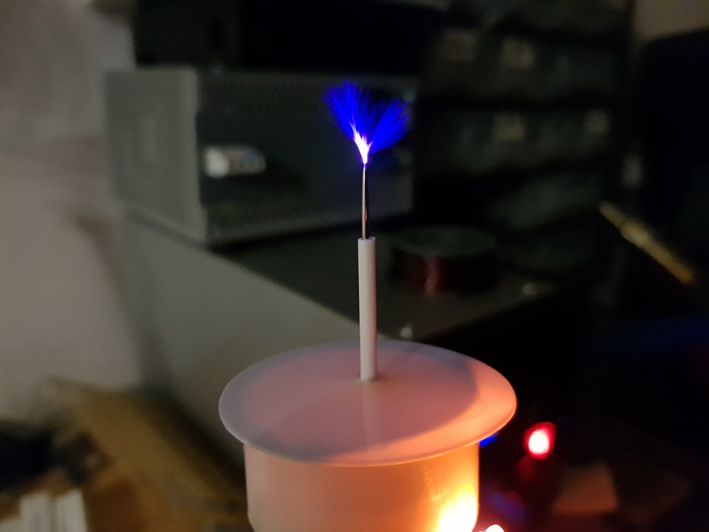
Since my streamer is not very large, to visually indicate the operation of the coil and the presence of high voltage, I added a small neon light bulb to the body of the coil.

Conclusion
Brovin's Kacher is an easy-to-replicate and interesting device for studying high-voltage discharges in different environments. The very principle of its operation is interesting and mysterious... After all, the voltages generated by the high-voltage coil, and these are thousands and tens of thousands of volts, do not damage the transistor, although they are directly applied to the base of this semiconductor device.
In principle, there is a scientific explanation for this mystery (and more than one), but still, the very principle of operation of the device remains a subject of debate among scientists and experimenters, as well as enthusiasts engaged in the search for Free Energy and studying the legacy of Nikola Tesla. Perhaps you will be the one to solve this riddle...
Introduction and general principle works by Kacher Brovin
Brovin's kacher is a type of blocking generator of electrical impulses with a relatively high frequency. The device can be assembled using various active elements, but most often bipolar or field-effect transistors are used during assembly. This device was invented by engineer Vladimir Ilyich Brovin in 1987. Moreover, it was invented rather by accident - Brovin was developing an electromagnetic compass that would allow one to determine the cardinal directions using sound. And as a sound generator, the engineer used a blocking generator he designed with a circuit feedback. The compass is working. But in the operation of the blocking generator, certain discrepancies with some laws of physics were noticed (for example, with the laws of Ampere and Biot-Savart, as well as with Kirchhoff’s law). That's how the kacher appeared.
Brovin came up with the name for his invention in 1996 based on the words “reactivity pump.” The author of the invention explains the operating principle of this or simply Brovin's kacher as follows:
In a conventional blocking oscillator, the transistor is turned on by the flow of current from a feedback coil in the base circuit of the transistor. In quality it is in a non-obvious way (since in theory the appearance electromotive force in the feedback coil the transistor can still open) will be closed all the time, and the current is generated due to the accumulation electric charges in the base of the transistor for further discharge when a certain threshold voltage is exceeded (the so-called “avalanche breakdown”).
There are a great many opinions and reviews about this invention: from enthusiastic to skeptical. Here is the opinion of the inventor himself, taken from the forum http://club.1-info.ru (the author's spelling and punctuation have not been preserved):
Kacher is a transistor (radio tube) device with phenomenal qualities. Cheap (device costs less than $1) and does not require special technologies. Knowledge about the properties of casters is sufficient for widespread use in almost any industry, including ballet.
Since 2005, the topic of kacers has been discussed on many forums (type “Brovin Vladimir Ilyich” in a search engine). The opposition is completely suppressed, pay attention to the dates - the spitting continues until 2006.
Recognition of the existence of a new method of controlling a transistor is obvious.
There is no practical application (there is, but very little). Isn't it time, gentlemen, entrepreneurs, to start making money from this, and for you, government officials, to collect taxes?
Anticipating the question “Why not yourself”? I answer: “Because the 68th went. It's too late, doctor." "What to do?". Choose a topic - for example, “autoelectronics” - create a laboratory and start converting everything that is electrical in a car, as well as its production technology, into quality ones.
Perhaps someday this will be the case, but for now Brovin’s invention is just a fun toy for enthusiasts that has not found mass application in electronics or industry. Now let's move from theory to practice - let's make a Brovin kacher with our own hands.
Below is one of the diagrams of this quality device:

To make a Brovin kacher we will need the following parts:
- — 1 ferrite ring (height 0.7-0.8 cm, outer diameter 1.5-2 cm, inner diameter 0.5-0.7 cm);
- — 1 trimming resistor at 220 Ohm 0.25 W (R1);
- — 1 resistor at 1 kOhm 0.5 W (R2);
- — 2 transistors KT805 (with radiators) (VT1, VT2);
- — 1 rectifier diode 1A;
- — 1 capacitor 10000 uF 50V;
- — winding wire, 0.25 mm thick;
- - copper wire square section, thickness 1.5 sq. mm (for primary coil);
- - square wire, 0.5 square meters thick. mm;
- - a small piece of plastic (can be cardboard, but not metal or metal-plastic!) tube, an ordinary plumbing pipe 1-1.5 cm thick and 20-30 cm long is quite suitable;
- - a tube, 4-7 centimeters thick (for the primary winding, you can take half a liter plastic bottle);
- - planks for making a stand.
Stages of assembling the Brovin kacher
- 1. For the primary coil, take a square copper wire and wind it on any tube with a diameter of 4-7 centimeters - make 4 turns. We take out the tube, stretch the wire in length so that the height of the winding is 10-15 centimeters (about a third of the height of the secondary coil). Ready.
- 2. For the secondary coil, we wind a thin winding wire around a plastic pipe, making 800-1000 turns. Every few centimeters it is recommended to apply glue to the fresh turns, otherwise the winding may get confused and tangled. We install the primary winding around the bottom of the secondary coil (see photo below).
- 3. We assemble the remaining elements according to the diagram. The pipe must be secured in a vertical position; to do this, its end can be glued to the base (a board or even an unnecessary DVD). If the circuit does not work, try swapping the leads of the primary coil. It should help.
- 4. Adjustment of the assembled quality is carried out by adjusting the trimming resistor R1. Also, do not forget to install radiators on the transistors - they get quite hot.
Have you collected it? With bated breath, we bring an energy-saving lamp to the coil.

But this option is not the only possible one. Enthusiasts and Brovin himself developed many circuits, with various transistors, two or three coils, etc.
A very interesting device called the “Brovin Kacher” is very popular among radio amateurs. With its help you can observe spectacular corona discharges, lightning, and plasma arcs. Many people on the Internet call the kacher a Tesla coil, but these are two completely different devices with different operating principles. In this article we will talk specifically about the Brovin quality device, perhaps the simplest high-voltage device that you can think of.
Brovin's quality scheme

The circuit is extremely simple, containing only one transistor, a pair of resistors and a pair of capacitors. Capacitors serve to filter the supply voltage, one of them should be electrolytic with a large capacity (470-2200 µF), and the second ceramic or film with a low capacitance (0.1-1 µF), to smooth out high-frequency interference. Two resistors form a voltage divider, one of them should have a small resistance (150-200 Ohms), and the second should have about 10-20 times more resistance. In this case, a trimming resistor can be placed in series with the high-resistance resistor to adjust the quality to the maximum discharge length. On printed circuit board, attached to the article, an installation space is provided for it. Almost any powerful transistor can be used in the circuit n-p-n structures. Transistors KT805, KT808, KT809 have proven themselves well. You can also experiment with field ones and install, for example, IRF630, IRF740. The length of the discharges largely depends on the choice of transistor. The transistor must be installed on the radiator, because it stands out a large number of heat. L1 in the diagram is the primary coil, and L2 is the secondary coil, the high-voltage discharge is removed from it.
Device board
The payment is made using the LUT method, a printable file is attached. Terminal blocks are provided on the board to connect power wires and coil outputs.

Download the board:
(downloads: 167)
Manufacturing of a secondary (high voltage) coil
First of all, you need to make a secondary coil. With it, everything is simple and concrete - the more turns, the greater the voltage, and, accordingly, the longer the discharges. You can use enameled copper wire with a cross section of 0.1 - 0.3 mm. It is very convenient to use a sewer pipe as a frame for the secondary winding; the optimal diameter is 5-7 cm. You need to wind the wire turn to turn, as carefully as possible. It is advisable to use a single piece of wire so that there are no joints. But if the wire breaks during the process, it’s okay, you can solder the torn piece to it, carefully insulate it and continue winding the turns, it will work in any case.
To speed up the winding process, you can install the pipe on two supports on the left and right so that it rotates freely on them. This will make winding the wire much easier. If you need to leave during work, you can secure the tip of the wire with tape, then you can come back, peel off the tape and continue winding. Under no circumstances should you let go of the tip of the wire, otherwise the tension will disappear, the turns will separate and you will have to start all over again.

After the coil is wound, the turns of wire must be fixed to the pipe. It is best to use a transparent varnish, then the reel will look very beautiful. I coated the coils with regular wax, it did the job, now it will be much more difficult to accidentally damage the thin wire.

A regular wire should be soldered to the lower end of the wire and carefully fixed at the edge of the pipe.

At the upper edge of the pipe there is a so-called “terminal” - the place from which the corona discharge will “emanate”. It is advisable to make it sharp, then the discharge will be concentrated at the tip of the needle. I secured a bolt to the edge of the pipe, and screwed a dart tip onto the bolt, as can be seen in the photo. The secondary coil is ready.

Making the Primary Coil
The primary coil contains 2-5 turns of thick copper wire, with a cross-section of 1.5 - 2.5 mm. It should be located around the secondary coil, its diameter should be 2-3 cm larger. For the frame of the primary coil, you can again use a sewer plastic pipe, you just need to take a piece of pipe with a diameter and length greater than for the secondary one. At a distance of 10 cm from the top of the pipe, two holes are drilled through which the copper wire is threaded. The length of the discharge strongly depends on the number of turns, so their number is selected experimentally.
The wire from the turns themselves must be brought to the bottom of the coil, passing them inside the pipe. Be sure to fix it with glue. The primary coil is ready.

Assembling the Brovin quality
After the coils are wound, you can put everything together. Two round pieces with holes in the center are cut out of penoplex. The secondary coil should fit tightly into the central hole, and the outer diameter of the workpieces should match the diameter of the primary coil.
We place the round blanks inside the large pipe, and then insert the secondary coil into them. If necessary, you need to fix them with glue. The wire from the secondary coil must be routed to the bottom of the large pipe.


Two holes are drilled at the bottom of the large pipe, one for the power connector, the second for the toggle switch.

Now all that remains is to connect the board to the power supply, placing a toggle switch in the positive wire gap, and connect the coil leads.

When all wires are connected, you can check the functionality of the device. Carefully apply voltage to the board. If a small light appears on the terminal, it means the camera is working. If the kacher refuses to work even when the supply voltage increases, the leads of the primary coil should be swapped. Now you can experiment with the number of turns in the primary coil, move the coils relative to each other, finding a position at which the discharge will be maximum. The power supply voltage range of the camera is very wide - a small discharge appears already at 12 volts. As the voltage increases, it increases, and along with it, the heat dissipation on the transistor increases. Therefore, it is imperative to monitor the temperature of the radiator, because an overheated transistor will not work for a long time.
The last thing that remains is to install the board with the radiator inside the large pipe, in its lower part, and place the toggle switch with the connector in the already drilled holes.


This camera looks very impressive even when turned off. You can touch the corona discharge with your finger, it is quite safe, because the current from such a discharge flows along the surface of the skin without penetrating inside. This effect is called the skin effect, it occurs due to high frequency quality work. During long-term operation, a large amount of ozone is released, so you should turn on the power generator only in ventilated areas. Also, do not forget about the strong electromagnetic radiation, which is created around the device. It can damage other electronic devices, so you should not leave phones, cameras, or tablets nearby. The electromagnetic field created is so strong that gas-discharge (or, more simply put, energy-saving) light bulbs light up on their own near the coil.

For a long time I wanted to assemble a small Tesla coil or a Brovin kacher in order to do various experiments. A simple kacher did not inspire me, because the arcs from it were scanty. The idea was born to replace bipolar transistor, field worker.
The current consumption of the structure is from 1 to 2-3 amperes depending on the supply voltage. Supply voltage 100-250 volts, if you use the appropriate field-effect transistor then the voltage can be increased.
For beginners, I’ll immediately say that streamers can squeeze a maximum of 20 centimeters. (here in the article there are streamers of 12-17 centimeters).
The operating principle is based on the generation of high-frequency pulses by a field operator.
You can replace absolutely everything in the circuit, but this will affect the operation of the device.
The device does not need configuration if everything is assembled correctly, but if it doesn’t work, then we look for a jamb in the circuit. If it doesn’t work and everything is assembled correctly, then we swap the outputs of the secondary, it should help. In order to accelerate the circuit and make the streamers larger, we make an oscillatory circuit in the L2 coil circuit. If you pick up a capacitor, the arcs will be loud and long. We select bias resistors from 10-60 kilo-ohms, power does not matter. Coil L1 is a choke from the lds, it also needs to be selected, the primary from the transformer will also work.
The cost of the device was 560 rubles, if you buy absolutely all the parts.
And of course a photo.


List of radioelements
| Designation | Type | Denomination | Quantity | Note | Shop | My notepad |
|---|---|---|---|---|---|---|
| VT1 | MOSFET transistor | IRFP460 | 1 | To notepad | ||
| VD1 | Diode | KD202B | 1 | To notepad | ||
| VD2, VD3 | Zener diode | KS147A | 2 | To notepad | ||
| C1 | Electrolytic capacitor | 100uF 450V | 1 | To notepad | ||
| C2 | Capacitor | 1uF 400V | 1 | To notepad | ||
| R1 | Resistor | 40 kOhm | 1 | To notepad | ||
| R2 | Resistor | 1 kOhm | 1 |