Powerful 200 dB amplifier circuit. Main technical characteristics of STK4050
The proposed scheme is designed to "power" integrated power amplifiers based on TDA7293 and TDA7294 microcircuits with the help of several external components. A distinctive feature of the proposed scheme is simplicity and lack of adjustment.
Many of those who assembled amplifiers on TDA7293 and TDA7294 microcircuits were faced with the fact that the real microcircuit does not hold the power declared in the Datasheet. One of the possible reasons is poor-quality Chinese microcircuits. However, they usually work well for a high-resistance load, from which we can conclude that the crystal simply overheats under load, and the vaunted thermal protection (as well as short-circuit protection) also works “in Chinese”: it does not protect against anything. A careful study of the microcircuit leads to the same conclusions - the ability of this case to divert more than 40-50w from the crystal is highly doubtful. Well, except to cool it with liquid nitrogen ...
Short circuit protection is also specific there - when working on a complex load (a real subwoofer), peak currents even at half power exceed the protection threshold, which causes a nasty crackle in the sound ... At the same time (a sad experience, alas) - after a couple of minutes, the microcircuit is still turns into a cloud of smoke, despite the best efforts of the internal protection circuit ...
And the very idea of TDA7293 and TDA7294 is very attractive - a small-sized module with a power of 100-130 W with a very decent sound (not high-end, but quite high-fi...). This is an amplifier for a home subwoofer, and an amplifier for a hybrid guitar apparatus, and 2-3 such modules with appropriate speakers are enough to sound small rooms ... It's a pity that it does not work, as the manufacturer's documentation promises ...
The idea to use the TDA7293 as a preamplifier with an external output stage was completely banal and obvious, and even reflected in the documentation for the microcircuit. The solution proposed by the manufacturer can be called simple with some stretch, and most importantly, it only reduces the power dissipated by the microcircuit, but does not increase the current delivered to the load ...
Therefore, it was decided to make the “help” in a different way, and, of course, as simple as possible. I’ll note right away that this solution is not in the audiophile style “only lamps and always in class “A”” ... No special measurement of distortion was carried out, but the circuit has no distortion visible on the screen and clearly audible to the naked ear, especially since the circuit was originally intended to work with subwoofer.
The input part is practically a typical TDA7293 inclusion. Slightly changed the circuit for generating control voltages on 9/10 pins of the microcircuit for simplicity. I will pay attention to the separate "grounds" of the input circuits and electrolytes for power and load! If you have a single-channel amplifier with a separate power supply and the signal is fed directly to the input of the TDA7293, then the grounds can not be separated (as is done on most printed circuit boards offered with the TDA7293). But if several channels are fed from one source, and even the signal comes from some kind of crossover, the “ground” of the power supply of which is also attached to the “ground” of the power amplifier, then questions arise like: “Why is it phoning? I shielded everything!” The track on the signet needs to be cut, and a 100 ohm SMD resistor can be soldered directly to the cut. The signal ground must be stretched with a separate wire (you can use a shielded wire screen) from the signal source. Since the external output stage operates in class B, to eliminate the “step” in the output signal, the resistor R8 is chosen to be relatively low-resistance (0.75 Ohm), and the highly linear TDA7293 works predominantly in the output current range up to 1 A. When the output current of the amplifier increases to about 1 A, the output transistor opens smoothly and the output current of the TDA7293 is limited by the sum of the base current of the output transistor and 1 A through R8. The value of R8 should not be further reduced - this will not noticeably increase linearity, and the power dissipated by the TDA7293 will increase. Capacitor C9 eliminates RF excitation and further reduces switching distortion of the output stage (more precisely, it allows the RF components from the TDA7293 output to go directly to the load, which quite effectively compensates for the "step" of the output pair of external transistors). In the first variant, one pair of output transistors was used, while the power at the resistive load equivalent of 4 ohms turned out to be 200 w sine when powered +/-55 v at idle. Under load, the power went down to about 48 v (power was supplied by a TC-360 transformer with a rewound secondary winding, filter capacitances were 15,000 microfarads each). Since the real load is complex, a second pair of transistors and resistors R9 and R10 were added to improve reliability to equalize the currents between the pairs (if you need power less than 200 W, it is quite possible to limit yourself to one pair of output transistors. In this case, resistors R9 and R10 can be omitted). The feedback circuit is connected to the emitters VT1, VT2. This increases the output impedance of the amplifier by 0.08 ohms and, in my opinion, is not a defect. If the feedback is connected to the load, the output current of the TDA7293 will not be limited to 1 A, but will continue to grow, albeit slowly.
I recommend connecting acoustics through a relay with a connection delay circuit and protection against direct voltage at the output - the output stage does not have short circuit protection and in the event of any cataclysms there is a decent chance to damage the acoustics. In addition, on the free contact group of the same relay, I assembled a current limiter of the power transformer when turned on (a wire resistor of 100 ohms with a power of 10 W is included in the power supply circuit of the 220V transformer, closed by the free contacts of the relay) - an extremely useful thing with powers over 100 w. The usefulness of such a solution lies in the smooth increase in the supply voltage of the amplifier when turned on, and most importantly, in limiting the current from the network at the time of turning on. A further increase in power is quite possible: the allowable power supply for the TDA7293 is +/-60 v, the number of output transistors can be increased accordingly.
Everything that was said about the TDA7293 fully applies to the TDA7294 - taking into account the lower limiting supply voltage and a different scheme for connecting the voltage boost capacitor. My experience shows a slightly higher reliability of the TDA7294, but perhaps this is a consequence of the low-quality Chinese-made TDA7293 that have recently spread ... both current overload and voltage clipping - just attach an LED with a current-limiting resistor to the 5th output of the microcircuit, which is quite convenient.
The proposed solution - an external output stage - does not require tuning if assembled from serviceable components, because the quiescent current of the output transistors is 0. A serious drawback of the proposed circuit is the lack of protection against short circuits in the load - when an external output stage is connected, the built-in circuit does not work (fairness for the sake of it, it should be noted that the built-in circuit in the recommended inclusion never saved the microcircuit from burning out for me ...). However, if the proposed amplifier is built into, for example, a subwoofer, due to the lack of external connections to acoustics, the probability of a short circuit is negligible, and you can turn a blind eye to this drawback ...
It is possible to further reduce the power dissipated by the TDA7293 - increase R8, but this will inevitably increase the distortion introduced by the output stage (I believe that for use with a subwoofer, this is quite acceptable, especially since at low OOS frequencies, the microcircuits quite effectively compensates for them).
Structurally, it is convenient to mount the entire assembly directly on the heatsink - the microcircuit with the board is mounted in close proximity to a pair of output transistors (through mica gaskets and with the help of thermally conductive paste, of course), all elements except R8 and C9 are located on the microcircuit board, and
It is convenient to solder R8 and C9 directly to the terminals of the transistors.
This is what the layout of the variant with one output pair of transistors looked like:

Perhaps - a similar solution has already been proposed before - I did not conduct a “patent” search ...
List of radio elements
| Designation | Type of | Denomination | Quantity | Note | Score | My notepad |
|---|---|---|---|---|---|---|
| Audio amplifier | TDA7293 | 1 | Or TDA7294 | To notepad | ||
| VT1, VT3 | bipolar transistor | 2SC5200 | 2 | To notepad | ||
| VT2, VT4 | bipolar transistor | 2SA1943 | 2 | To notepad | ||
| R1 | Resistor | 33 kOhm | 1 | To notepad | ||
| R2 | Resistor | 680 ohm | 1 | To notepad | ||
| R3 | Resistor | 12 kOhm | 1 | To notepad | ||
| R4, R5 | Resistor | 33 kOhm | 2 | To notepad | ||
| R6 | Resistor | 47 kOhm | 1 | To notepad | ||
| R7 | Resistor | 100 ohm | 1 | To notepad | ||
| R8 | Resistor |
This scheme (for testing) was brought to me by a familiar DJ. He doesn't even know where he got it from. But after assembly, the circuit was very pleased with its characteristics. Therefore, I do not unfoundedly recommend collecting it to everyone.
Amplifier circuit
Details:
R1,R11 1K
R2 36K
R3 240
R4-R5 330
R6-R7 20K
R8-R9 3.3K 0.5W
R10 27, 2W
R12-R15 0.22 5W
R16 10K
C1 0.33mkF
C2 180p
C3-C4 10mkF 25V
C5-C7 0.1mkF
C8 0.22mkF
C9-C10 56p
VD1-VD2 KS515A
VT1 KT815G
VT2 KT814G
VT3 VT5 VT... 2SA1943
VT4 VT6 VT... 2SC5200
Instead of the parts indicated in the diagram, you can use the output transistors KT8101A and KT8102A. Their number can be any.
Download scheme and printed circuit board amplifier 28 kB (SLayout)
Power Supply
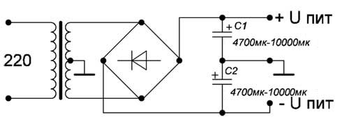
Bipolar power supply circuit
From the author:"The circuit is simple: a transformer, a diode bridge and a pair of capacitors. A transformer is needed in terms of power a little more than the total power of the channels, and capacitors - the more capacitance, the better. Only calculate the voltage of the windings so that the capacitors are no more than 50 volts."


It is possible to build an amplifier with transistors, but it is much easier and faster to build an amplifier based on Sanyo's STK40xx series hybrid integrated circuit. The amplifier is obtained with high sound quality and low noise.
The maximum output power of the amplifier, for example, on the STK4050 is 200 W!
The sound is of good quality. The amplifier can be used in home theaters, computers, etc. can also be used as a subwoofer amplifier. For the stereo version, you need to assemble two such amplifiers. Load resistance 8 ohms. The chip must be installed on a good heatsink through thermal paste. The power and output traces on the PCB must be as wide as possible.

Main technical characteristics of STK4050:
- Maximum allowable supply voltage +/- 95 V
- Rated supply voltage +/- 65 V
- Rated output power 200W
- Power dissipation (P out. = 200 W.) 130 W
- Harmonic coefficient (P vor. = 200 W.) 0.3%
- Rated load impedance 8 ohm
- Input impedance 55 kOhm (P out = 1 W, F = 1 kHz)
- Frequency response (+0, -3 dB) 20 Hz - 50 kHz
- Voltage gain 40 dB
- Sensitivity 350 mV
Schematic diagram of the amplifier on STK4050

Peculiarities STK4050:
- Compact and slim body
- STK series has 18 pins maximum power per channel from 120W to 200W
- Simple heat sink design
- The current application of a mirror circuit reduces distortion to 0.08%
- Load shutdown for thermal protection and short circuit protection, as well as noise suppression, when power is turned on / off
Power supply and internal circuit STK4050

Amplifier circuit board

Finalization of the circuit on STK4050

Table of characteristics of GIS STK40XX

P O P U L I R N O E:

How to provide a loud-speaking connection, say, two points remote from each other by a considerable distance? A similar task arises in a school, a pioneer camp, in a small village, or in remote rooms of a house. And in all such cases, an intercom comes to the rescue.
lightsaber(Eng. Lightsaber) - this fantastic weapon is known to many from the fantastic Star Wars saga. It can be found in science fiction films and stories.
Using a quality amplifier will increase the detail and realism of your favorite music reproductions.
Do-it-yourself amplifier 100W / 200W
A variable resistor of 47 kΩ is placed at the input of the first transistor, which also reduces the noise level of the amplifier.

At the minimum volume, the noise is not heard, and at the maximum it is masked by a useful signal.

Product parameters: 150W into 4 ohm load and 100W into 8 ohm load.

The second is devoid of the disadvantages of the first, with regard to noise. The amplifier operates in class B, the diodes D2-D3-D4 set this mode of operation to the output transistors VT4-VT5.

Transistors VT3-VT5 are installed on the heat sink, using thermal paste through insulating gaskets.

Do-it-yourself ULF can be used in an active speaker, the bass reproduction subwoofer is excellent.

In this article on our website www.site we will tell you how to assemble it yourself, which will save you on buying ready-made models.
What is the best power amplifier?
There is no consensus on what type of amplifier is best. Currently, it is possible to self-assemble two types of audio amplifiers:
Lamp models were popular in the recent past. They are characterized by increased size and increased power consumption. But at the same time, these are superior to their competitors in sound quality.
Transistor amplifiers have a compact size and low power consumption. At the same time, they provide excellent sound quality.
How to get started?
First you need to decide on the power of the future amplifier. The standard power parameter for using an amplifier at home is a level of 30 - 50 watts. If you need to make one that will be used for large-scale events, the power can be 200-300 watts.
For work, we need the following tools:
- Screwdriver Set.
- Multimeter.
- Soldering iron.
- Material for the manufacture of the body.
- Electrical parts.
- Textolite for printed circuit board.
In fact, printed circuit boards are the basis for the future amplifier. Collecting it at home is not difficult.
To make a printed circuit board with your own hands, you will need:
- Textolite with copper foil.
- Detergent.
- Household iron.
- Self-adhesive Chinese film.
- Laser printer.
- Drill for working with the board.
A piece of cotton cloth or gauze pad. We cut out the blank of the future board from the textolite. Leave a centimeter margin on each side. Using a detergent, it is necessary to process a piece of textolite so that the copper foil gets a pink color. We wash the workpiece we have made and carefully listen to it.
We glue the self-adhesive film to an A4 sheet. We print the blank of the future board on the printer. It is recommended that you set the toner supply to the printer to maximum. On the work surface, lay plywood, an old book and top the board with the foil up. We cover everything with office paper and carefully warm it up with a hot iron. It takes about 1 minute to warm up.
We apply the printed circuit from a sheet of paper to the heated board. We cover the top of the board with a sheet of paper and heat it with an iron for 30 seconds. Smoothes the pattern with a swab in transverse and longitudinal movements. Wait for the workpiece to cool, after which you can remove the substrate from it.
How to charge a fee?
For manufacturing, it is necessary to put on the board all the tracks used for the radio components. You can do this work with a CD marker, and then etch the board with ferric chloride. Unfortunately, ferric chloride has a high cost, so many people replace it with a self-prepared solution of table salt and copper sulfate.
The proportions of the prepared mixture:
- Kitchen salt - 200 grams.
- Copper sulfate - 100 grams.
- 1 liter of warm water.
After mixing all the components, lower the fat-free and clean nails or metal products into the container.
The Metalist company specializes in the manufacture of various types of metal structures. The company's clients are offered both standard metal structures and the possibility of their production according to individual orders. Details and metal products to order are offered at affordable prices, and their production is carried out in the shortest possible time.
Assembling the amplifier
At the initial stage, the used radio components are installed on the printed circuit board. Consider the polarity and power of all components used. Perform this work in full accordance with the existing diagram, which will avoid the danger of a short circuit. After completing the assembly of the board, you can proceed to the manufacture of the case.
The dimensions of the future amplifier depend on the dimensions of the board and the power supply used. You can also use ready-made factory cases from old amplifiers. We can recommend that you make the case by hand from chipboard. Subsequently, you can easily finish the manufactured case with veneer or self-adhesive film.
Before the final assembly, it is necessary to make a test run of the amplifier. The power supply, board and all components used are installed. This completes the work of making an amplifier with your own hands, and you can enjoy high-quality sound.
The basis of the amplifier is the K140UD708 chip, the preliminary stage is built on domestic transistors of the KT814 / KT815 series, preferably with the letter G, the transistors can be replaced with other complementary pairs that are similar in their parameters to those indicated. This circuit belongs to the class of rather expensive amplifiers, stereo versions of such amplifiers cost from $ 200, but it will cost ten times less to assemble, therefore - if your hands grow from the right place, then you can assemble it yourself! Schematic diagram and circuit board of a 200 watt audio power amplifier in the figures below:

Resistors:
R1 R11 =1k
R2=36k
R3 = 240 off
R4 R5 = 330 off
R6 R7 = 20k
R8R9=3.3k0.5w
R10=27om2w
R12 R13 R14 R15 = 0.22from 5w
R16=10k
Capacitors:
C1 \u003d O.ZZtk
С2=180r
SZ C4= 10mk25v
С5 С6 = 0.1 tk
С7 = 0.1tk
С8 = 0.22tk
С9-С10 = 56r
Zener diodes:
VD1 VD2 = KC515A
Transistors:
VT1 = KT815G
VT2 = KT814G
VT3VT5 = 2SA1943
VT4 VT6 =2SA1943

The output stage transistors can be replaced with domestic KT8101A and KT8102A, you can increase their number in order to increase the output power of the amplifier, but do not forget to increase the supply voltage. It is important that the transistors are identical in characteristics and different structures.

The output transistors are installed on a heat sink, it is desirable to choose a larger one, and be sure not to forget about the insulating gaskets of the transistors. With the specified supply voltage, our amplifier is capable of delivering up to 200 watts of pure power to the load, by adding two more pairs of output transistors, you can increase the power to 450 watts, but then the amplifier supply voltage also needs to be increased to +/- 70 volts.