Adapter for TV antenna diagram. Digital antenna with amplifier. Using a Polish antenna for DVB-T2. Power supply - adapter for antenna amplifier
Antennas for receiving digital terrestrial television (UHF antennas) can be either active or passive. Active antennas are antennas with a built-in or external signal amplifier. Passive antennas do not have any amplifier, and are capable of receiving a signal at a short distance and with relatively direct visibility to the transmitting equipment.
Power is supplied to active antennas in different ways:
By antenna cable;
via additional cable ( power unit connects to a 220 Volt outlet);
through USB interface TV.
The antenna cable now powers most antennas sold. The convenience of this connection method is undeniable - it’s simple turn on the “antenna power” in your DVB-T2 receiver and everything works right away (example). But if you have a TV with DVB-T2 support, everything is more complicated, but more on that later.
Connecting via an additional power cable is also relatively a large number of receiving equipment. For example, the antenna DELTA DIGITAL.12V - soon you will be able to see its review on our website.
Active antennas powered via a USB interface have appeared relatively recently. Let us note right away that if you have a TV with a built-in DVB-T2 tuner, this is the most successful connection option. As an example, let’s take the active antenna “REMO BAS-5310USB HORIZON”, a review of which will also appear on our website.
If turning on the power to the antenna in a digital DVB-T2 receiver is simple, then how to supply power to the antenna on the TV? In leading brands (such as LG, SONY, Philips, Samsung) the “antenna power” item is simply missing.
How to turn on the antenna power on an LG TV:
The response from LG support was as follows: our equipment does not have such a function.
How to turn on the antenna power on your Philips TV:
Similarly to LG, these TVs did not have such an item in the menu.
This begs the question - how to supply power to the active antenna in modern TVs? There is a possibility that power is always supplied to the antenna, i.e. When you connect the antenna, the TV immediately outputs +5V to the antenna. But this is not correct, because when a separate amplifier is turned on, a short circuit will occur. The option is no longer available.
It turns out that with modern TVs you can use either passive antennas or antennas with an external power supply. And now is the time to remember about the active antenna, the power of which is supplied via the USB interface - this is either an antenna "REMO BAS-5310USB HORIZON", or its analogue.
Also, any 5V antenna can be powered from the USB output of the TV, even if it was not originally designed for this. Company "REMO" proposes to switch all antennas to this method of power supply and abandon external power supplies altogether. The REMO BAS-8001 USB injector was developed especially for this purpose. You connect the antenna to the injector, connect the injector to the TV and forget about the bulky and in this case unnecessary power supply. Let us clarify that this method is only suitable for 5V active antennas.
The vast majority of antennas for receiving television programs include a signal amplifier. Like any electronic device, it requires a power supply. main feature– use of an antenna cable to simultaneously transmit the useful signal and supply voltage. This principle of organizing food antenna amplifier has long been accepted as a de facto standard by most manufacturers of antennas and amplifiers for them. This is due to the fact that the distance from the amplifier to the power source is large, but no additional cable to the power supply is required.
Amplifier purpose
Reliable reception of programs for viewing channels on terrestrial television using a conventional antenna is only possible at a short distance from the transmitting center. In all other cases, the active antenna is supplemented with a reception amplifier. As an example, we can cite Polish antennas, which have become very widespread, and Delta-type antennas.


The main function of TV antenna amplifier:
- increasing the level of the useful signal to acceptable values;
- reduction of interference level.
These qualities are listed because the quality of reception is affected not only by the magnitude of the useful signal, but also by its relationship to the level of interference. Based on this consideration, the antenna amplifier is located in close proximity to the antenna, often entering directly into its structure.
The power supply voltage for the antenna amplifier is supplied through the antenna cable. To isolate the useful signal, an antenna, either Delta or any other, is connected to the TV via an adapter. Some TV or tuner models have an antenna socket that already contains voltage. Thus, the need for a power supply and adapter is eliminated, although this does not exclude the possibility of using them. To do this, there must be an item in the TV settings menu that allows you to turn off the antenna power through the antenna input.
Important! The simultaneous supply of power from the antenna socket and the external power supply is not allowed, as this may lead to failure of one or more devices. At best, the quality of reception will suffer.
Power supply parameters
The antenna amplifier requires a power supply with the following parameters:
- constant pressure power supply from 9 to 12 volts;
- current value is not more than 100 mA.
As a result, the power of a TV power supply is a few watts, so it can have very small dimensions.

Power supply device
In the vast majority of cases, the power supply for a television antenna consists of a step-down transformer with a bridge rectifier, a filter capacitor and an integrated voltage regulator.

The output voltage of the transformer is about 12-18 V, preferably closer to the maximum value. Why this is so will be discussed below. An integrated circuit of type 7812 is used as a stabilizer. It has become very widespread due to its successful parameters and is available with different permissible power. In the power supply under consideration, you can use a microcircuit with minimal power (a more powerful one is quite acceptable, the criterion here is its dimensions). The domestic analogue of 7805 is K142EN8B (short name - KR EN8B). For normal operation of the circuit, it is necessary that the voltage at its input exceeds the output by at least two volts, and since after rectification and smoothing with a capacitor, the alternating voltage increases by about 1.4 times, the minimum voltage at the transformer output is about 10 V. The above limit is 12 V was selected taking into account a possible decrease in the network voltage.
The capacitance of the filter capacitor must ensure smoothing of voltage ripples. In this case, 220 uF is quite enough. The operating voltage of the capacitor should be several times higher than the rectified voltage, so it is better to take a capacitor rated at 35 V or higher. The LED serves to indicate the operation of the unit.
Very often, an antenna can receive both signals from a distant television center and from a nearby one. In this case, it is possible that the antenna amplifier begins to self-excite, that is, generate its own oscillations. Broadband antennas, which also include the Delta antenna, have a similar disadvantage. The quality of reception is greatly deteriorated. To get out of this situation, reduce the gain of the amplifier. This can be done by reducing the supply voltage. This option is shown in the figure below.

It can be seen that a variable resistor is included in the common terminal circuit (2) of the microcircuit. At the same time, the microcircuit itself has a different type - 7805 ( domestic analogue– K142EN5). At the minimum value of the resistor resistance, the stabilization voltage is equal to the passport value of the microcircuit - 5 V. By increasing the bias at the common pin, you can adjust the output voltage up to the input value.
High-quality adjustable antenna power supplies contain a stabilizer built using an adjustable integral stabilizer type LM317 (analogue - K142EN12). This variety is common, although the simplified scheme has proven itself well and has a lower cost.
Sometimes you can meet adjustable block power supply, in which the resistor is simply connected to the output conductor. This decision does not stand up to any criticism and is characteristic only of cheap Chinese devices.
Connection
The industrial adapter for connecting to a TV is connected to the power supply with a two-wire wire and has two terminals for connecting the antenna cable. To connect the cable, you need to cut it correctly. The cable that will be connected to the antenna consists of a central core, enclosed in plastic insulation, and a shield braid, which, in turn, is enclosed in insulation.
In order to connect the cable to the adapter, you must first carefully trim the outer insulation with a sharp knife at a distance of 2 cm from the edge, being careful not to trim the shielding conductors. Next, the insulation is pulled off the cable. Stepping back 15 mm from the edge, cut off the screen. The central wire with insulation remains. Now, stepping back 1 mm from the screen, very carefully trim the central insulation to a depth of several millimeters. By bending the cable several times at the cut site, you need to ensure that the insulation bursts in a circle. Now it needs to be removed from the core.
Important! You cannot cut the insulation to its full depth, since the central core will break at the point of the cut.

The cut cable is inserted under the terminals of the adapter so that the core falls under the fastening nut in the central terminal, and the shielding braid lies under the wide terminal. Now you can tighten the terminal screws. The connection is ready.
Note! Do not allow at least one of the cores of the shielding braid to come into contact with the central terminal. The power supply will not fail (the microcircuits are protected from short circuit), but the supply voltage will not be supplied to the antenna amplifier.
Before connecting the antenna cable, it is advisable to check the output voltage of the unit. Its values must be within the specified norm and in no case more.
Basic faults
Amplifier power supplies rarely fail so much that they cannot be repaired. The most common loss of filter capacitance is observed. This malfunction manifests itself in the form of wave-like image distortions due to the penetration of voltage ripples into the amplifier and antenna input of the TV. The reason is usually a poor quality capacitor. Externally, it will have a convex end (must be flat). For repairs, it is enough to install a similar one with a capacity of 220-500 µF at a voltage of 35-50 V.
The absence of output voltage when there is a stabilizer chip at the input indicates a malfunction of the latter. For replacement, you can install any similar microcircuit (analogues were indicated above).
In cases of network voltage surges, the step-down transformer fails. Unfortunately, repairing it will require rewinding the windings, which is difficult to do at home. But if the transformer windings are made on separate coils, then it is possible not to resort to rewinding. Typically there is a fuse built into the primary circuit. To get to it, you need to carefully, trying not to damage the conductors, cut off the outer insulation of the primary winding, which is wound with a thin wire and has a large number of turns, and therefore is much larger than the secondary. A fuse looks like a resistor and if it blows, it has infinite resistance (a working fuse has zero resistance). A faulty fuse is bridged with a thin wire with a diameter of 0.05-0.07 mm.
The diode bridge is made on rectifier diodes with a large margin of voltage and permissible current, so it almost never fails.
Much more often, the junction between the cable and the adapter becomes loose, resulting in loss of contact with the central core, or short circuit with the shielding braid. In this case, you need to connect the antenna cable efficiently and reliably.
To summarize, we can say that most consumers should not see a problem in how to properly connect the power supply or even repair it themselves. The most important thing is attentiveness, accuracy and desire.
Video
Unfortunately, many regional television companies broadcast through very weak transmitters. For this reason, manufacturers began to produce amplifiers for antennas quite High Quality at reasonable prices. Only the power supply for an antenna amplifier sometimes cannot boast of durability and operational reliability.
Due to its high sensitivity to thunderstorms and 24/7 uninterrupted operation in general, it often overheats, consumes more current and ultimately fails. A malfunction of the stabilizer renders the entire amplifier unusable.
The Perovo TV company took care of its customers, promptly responding to their wishes. In this section, we have collected antenna amplifier power supplies, which are economically profitable to buy, because they are characterized by low power consumption. In addition, the power supply for the antenna amplifier assumes a high degree of reliability and safety.
Manufacturers provide 2 types of devices to markets - an unregulated antenna amplifier power supply and an adjustable one. The latter makes it possible to smoothly change the voltage at the input of the unit in the range from 2 to 14 V, adjusting the degree of gain. In addition, the adjustable antenna amplifier power supply has some properties that make it stand out on the positive side:
- Has protection against short circuits and overloads.
- Powerful microcircuits increase the reliability of the device.
- Due to the stabilizer, a constant voltage is produced, ensuring normal operation of the amplifier.
- Compliant technical specifications by current.
Hi all
I would like to leave a small note here regarding the exclusion of the external power supply for the amplifier of a conventional Polish antenna, subject to the use of a set-top box for reception digital TV broadcast in standard DVB-T2 (for now).
Or, when using another device, for example, a TV with a built-in digital TV receiver that supports supplying a special active antenna with an amplifier to the antenna input.
The essence of the story. When I was looking at the settings of the set-top box for signal reception digital television in standard DVB-T / DVB-T2, then I found next to the manual and auto-tuning options an option to turn on the antenna power. The first thought is whether it will be possible to power the antenna amplifier with this voltage S.W.A., on the Polish antenna" grate"?
And I decided to try...
The experiment was carried out using an attachment for receiving digital TV - Rolsen RDB-502N, inside the device there is a board with something like this: YJ--DVB-78316M+MXL603, but this is not the whole name, I can’t remember completely exactly, nor the revision. Since I don’t have access to the device now, I won’t be able to look more accurately.
The point is not this, but the fact that before I measured the voltage at the antenna connector of the set-top box, I was counting on 12 volts. But no, I broke off, which was confirmed when disassembling the device - built-in pulse block power supply, supplies the set-top box with voltage only 5 volts. And to be precise - 5.2 volts, if my Chinese cheap multimeter didn’t lie.
There is short circuit protection: in the event of a short circuit in the antenna connector, nothing bad will happen - the set-top box processor immediately turns off the power, and the corresponding option in the set-top box settings is disabled. The field-effect transistor does not burn out from this, and I looked at how it works on the diagram: there is a second transistor, some kind of circuit feedback, and all this goes to the processor leg, to which the radiator is glued. Its name is on the board's marking; I did not peel off the heatsink itself.
This is approximately the voltage that was on the antenna connector... 5.2 volts Total
The point is that for this console there are room active antennas with an amplifier. True, I have never seen such antennas before. But they are
In this case, the set-top box is used in conjunction with an antenna " Delta"to which the amplifier is connected from Polish antenna "lattice", and if my memory serves me right, then it is installed there SWA-2000. Or SWA-49, I don’t remember exactly how I’ll get to the antenna - I’ll add to the article. No more than a digital repeater ~100 kilometers (the farthest repeater is the first multiplex).
So, it seems to me that the antenna native to this amplifier has better characteristics.
But in my case, using an antenna delta(the other one was not available, the mustache is connected too) - it also turns out to be more or less stable to watch the first and second multiplex, with the parameters " force"/"quality" - ~84% /~72% respectively. Provided that the antenna is installed at the height of the third floor.
And this one standard amplifier" S.W.A." - has a supply voltage 12 volts, from an external power supply, which in my opinion is quite " nasty", since it gets quite hot, which I don’t like, and I have to turn it on every time...
By the way - at idle, the power supply produces as much as about 19 volts, and when the connected amplifier is operating, the voltage drops to 11.6 volts,
Conclusion - the amplifier operates normally from 11.6 volts. But such a set-top box produces more than half as much - 5.2 volts, but, theoretically, this should not be enough, and the gain, with such power supply to the amplifier, should drop.
To find out, I, without any hope, dismantled the cable, turned on the antenna supply voltage in the amplifier settings, and quickly threw the cable onto the connector of the included set-top box ( accidentally shorting it a couple of times, anew o including power in settings), and everything worked!
However, the channel image ( Muz TV) disintegrated quite often, and force/quality were on the level 83% And 69% respectively. That is, the quality parameter fell, albeit not much, but there was no longer stability.
Then I got a little depressed and decided to order from China one of such boost voltage converters to five volts do 12 volts, but only when the set-top box was running, and began to prepare a board for connecting it.
Since I did not find a diagram on the Internet ( please send it if you have it) set-top boxes for receiving digital TV - Rolsen RDB-502N, then I had to figure it out myself.
Sorry for the lack of photos this time - I’m writing from old memory.
There, in the upper right corner, there is a radio module on the board, it is covered with an iron shield.
His internal structure I became not interested when I studied it roughly ( iron cover of the module screen on top - opens without problems), and found the field effect transistor, which is responsible for supplying power to the antenna connector when it is open.
I unsoldered it, and decided, just in case there were no problems, to solder only two legs of the transistor onto the board, and connected the third leg to the common wire, through a resistor 20 kOhm. There is such a resistor on this track going to the antenna, from which I disconnected the transistor, and to which I was going to connect the output from the boost converter.
Not directly, of course, from the converter to power the antenna, but through a formal filter, which I built using surface mounting, connecting a capacitor to the track going to the antenna 100 nF (marking 104), connecting its second leg to the ground, then connecting some small coil from an old but imported TV, which has an unknown inductance, because there is nothing to measure.
And on the other side of the coil, I again connected it all to a common wire, through the same non-polar capacitor to 100 nanofarads.
It may be excessive and perverse, but I'd rather be safe than sorry. There is no need for unnecessary interference, and the converter definitely creates it. He's impulsive.
So I thought that the output from the converter to the filter coil ( this is safe, nothing should burn from 12 volts, short circuit detection goes to the field operator, and 12 volts should not go to the processor of the set-top box. But it is not exactly. There’s just no diagram, but I spent a long time running a probe around the board and couldn’t find any connections to the antenna power path outside the receiving unit).
The converter will receive power from the field worker. The only thing I'm afraid of is going into a short circuit when the converter starts. We need an experiment.
And the common wire is the common wire.
Possible question: why do you need a converter, and why make 12 volts out of 5, if you can simply disassemble the power supply, and install a transformer from it inside the body of the set-top box, and supply 12 volts from it to the antenna connector, fortunately there is a lot of space inside the set-top box?
Yes indeed, free space There is a lot inside the console, and at least 8 of these transformers will fit in there, and the lid should close, and everything will work.
But you can’t do this, it’s stupid and a fire hazard - this transformer will work and heat up 24/7, even in standby mode. What for? Who will turn it off? ( if you are perverted like this, electricity bills are not critical, and you are not afraid of the increased possibility of burning down your home - do not forget to at least unsolder the field switch, otherwise, first, the 12 volt attachment will burn out)
However, there is an option to use some kind of relay or coil with a reed switch, with galvanic isolation (otherwise he'll kill the fucker ), which can be connected to the field device, so that either when the antenna power option is turned off, or in standby mode, the antenna power is turned off.
By the way, if you connect the relay coil to the line 5 volts- the meaning of this perverted idea will disappear, since 5 volts it's always there, it's the only food, it's duty... I think you get my point.
There are two more disadvantages if you bomb the transformer through the relay. First, there is no protection against short circuits in the antenna - which is obviously dangerous. And secondly, most likely, you will not find a relay that will not trigger short circuit protection with its coil. This can be circumvented by throwing in another more powerful field worker, but this is all a perversion.
It's better to try using a boost converter. The advantage of this approach will be the relative elegance of the solution, and the ability to adjust the voltage both higher and lower 12 volts- almost everything DC-DC converters have a voltage regulator. But naturally, higher 12 volts Powering the amplifier is not necessary and will lead to its failure.
In my case, everything happened even more interesting! Later, I tried to reduce the voltage by connecting a variable resistor of several kOhm, fortunately, the amplifier's current consumption is small, and the resistor should not have burned out. Nothing happened to the resistor, but when I started to rotate it while the console was running, when the voltage dropped up to 5 volts, I hardly noticed any deterioration strength/quality!
What happens, it is still possible to power the antenna amplifier from the set-top box without any converters, without deteriorating the reception quality and without unnecessary decoding errors - the image breaking up into cubes? Yoshka's meat, and I have already prepared everything for connecting something that has not yet been ordered from AliExpress boost converter...
Then I connected the leg back to that track, albeit through a filter - I did not remove it, I only removed the previously soldered resistor on 20 kOhm, since it is not needed yet, it already exists. Next, I unsoldered the power supply wire from the small board with the antenna connector, pulled out the board itself, removed the coil and capacitor that goes to the central core, and soldered the board back. Well, having pushed the cable further, unscrewing and completely removing the clamping square nut, I passed its central core there, soldering it directly to the central contact of the connector in order to avoid unnecessary signal loss, then twisted and pressed the braid back to where it was. It turned out that the signal from the central core of the cable immediately went to the set-top box, without any matching coils or capacitors.
I turned on the whole thing - and everything works great, no worse than from 12 volts from the power supply!
And the first time I hooked the cable directly to the connector" on the snot", apparently because snot and I got such an unsatisfactory result...
Now, the set-top box works without a power supply, isn’t that good?
Conclusion: you can try to power the antenna amplifier directly from the set-top box, and even if there is 5 volts there, everything will work - tested!
I've seen reviews online that it doesn't work at 5 volts, but that's a lie.
However, not all amplifier models will operate in this mode, and the issue of increasing the voltage is relevant. When I get to the antenna, I'll write down the amplifier model. 100 kilometers from the third floor with five volts of amplifier power to receive a digital TV signal - really. And if I used this amplifier with its native “grid,” it would be a hundred pounds, and visibility would be far from direct.
Please note that in nature there may be different devices for receiving digital TV that support 12 volts at the antenna input, and there are others without this function at all. Read the instructions for your receiving device. If it doesn’t support it, you can add it, but you’ll have to work on the circuitry yourself.
And remember - nothing is impossible (there are crooked hands).
Smart advice: it's better not to watch TV at all. There, on the vast majority of channels there is a complete lie, brainwashing of cattle, and a humiliating amount of advertising (super bonus - also regional advertising). Decide for yourself.
The article gives the characteristics of the “Polish” antenna, discusses its advantages and disadvantages, as well as practical recommendations for installation and configuration.
The antennas that you see in Figure 1 and the modernized version in Figure 2 are popularly called “Polish” due to the fact that they are manufactured and imported to Ukraine and other CIS countries from Poland.
“Polish” antennas gained their popularity thanks to:
- Cheaper: the antenna costs 35 UAH, and the antenna in Fig. 2 costs 55 UAH. (hereinafter prices are shown for the Kyiv radio market and may differ in the regions);
- Broadband: antennas cover the entire range of TV channels (MV, UHF) and VHF radio broadcasting;
- Ability to receive weak signals, which is ensured by the use of replaceable amplifiers.
Antenna Specifications:
- Operating frequency range 40 - 800 MHz;
- TV channels 1 - 12; 21 - 69;
- Width of the main lobe of the radiation pattern: vertical - 46°, horizontal - 27°;
- Own antenna gain 10 - 13.5 dB;
- Characteristic impedance 300 Ohm;
- Dimensions 800x600 mm;
- Weight 1.7 kg.
Below is appearance and the main components of the Polish antenna.

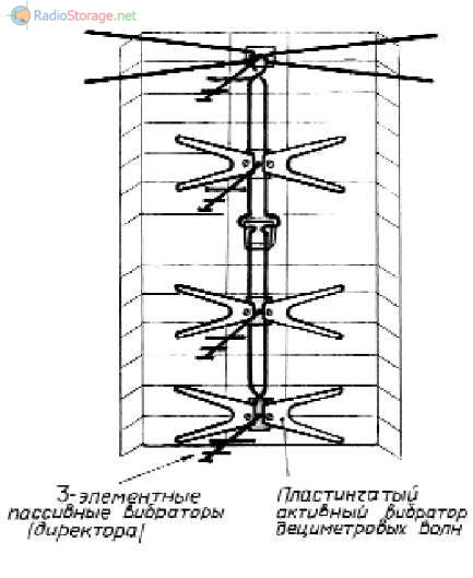
Fig.1. Polish antenna, basic antenna elements and connection.
The antennas shown in Figures 1 and 2 are sold disassembled and the buyer assembles them himself. The antenna kit (Figure 1) includes:
- Reflector with mounting kit for the mast - 1 set; two-wire line (waveguide) with mounting rail and mounting plastic boxes - 1 set;
- Passive vibrators (directors) - 4 pcs.;
- Active vibrators MV - 2 pcs.;
- Active vibrators UHF - 6 pcs.;
- Antenna amplifier (customer's choice) - 1 pc.;
- Power supply ~220 V/=12 V - 1 pc.;
- Antenna plug - 1 pc.;
- Instructions for using the antenna - 1 piece.
This kit for self-assembly of the antenna costs approximately 35 UAH.
The coaxial cable (feeder) is not included in the antenna package; it must be purchased separately. The recommended cable diameter is 6.8 mm, and its length is selected depending on the location of the TV and antenna. 1 m of cable costs 0.8 - 1.2 UAH.
Rice. 2. A modernized version of the “Polish” antenna.
The antenna amplifier is manufactured on a separate removable board, and the radio elements on it are mounted using hinged mounting. The board is placed in the center of the antenna in the mounting box (Fig. 1 a, c), which allows you to effectively amplify the received signal. If necessary, the amplifier board can be easily removed and replaced.
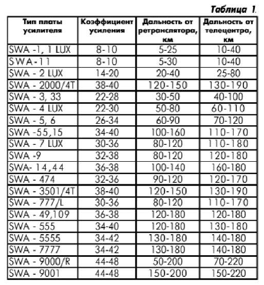
Antenna sellers have a large selection of antenna amplifiers. All of them are the same in size and differ only in the gain - from 5 to 48 dB. The number of modifications is constantly growing. The parameters of the most popular amplifiers are given in table. 1. The cost of each is 10-12 UAH.

Rice. 3. Antenna amplifiers.
It is sometimes difficult for a buyer to choose which amplifier is needed for his antenna. Using Table 1 and knowing the distance from the television center (repeater), you can approximately determine it, but it is better to consult with the seller of the antennas or take the advice of friends who have previously installed such an antenna.
It should be emphasized that the upper limit of the reception range indicated in the third and fourth columns of Table 1 is too high. It is impossible to ensure stable and reliable reception at a distance exceeding the line-of-sight range (80-100 km) by increasing the gain of antenna amplifiers.
To power the amplifier, you must have a power supply unit (PSU), which AC voltage 220 V produces constant 12 V (the power supply is included in the antenna kit). This voltage is supplied to the amplifier through an antenna plug and a coaxial cable (Fig. 1, c). And since the TV signal is also supplied to the TV through this cable, a capacitor is installed in the antenna plug to separate them.

Sometimes individual craftsmen, in order not to use a power supply, use 12 V from the TV. This is easy to do on ZUSTST color TVs Soviet made, however, I strongly recommend not to do this on foreign-made TVs.
An antenna amplifier amplifies TV signals, and all channels (frequencies) are amplified equally. In practice, sometimes situations arise when a TV signal that is highly skewed (in terms of power) is induced in the antenna.
This happens when some channels are emitted by high-power TV tower transmitters, while others are low-power. The antenna amplifier of the antenna, located close to the television center, equally amplifies all channels and outputs a powerful, highly skewed (in power) TV signal to the TV. The AGC of the TV cannot suppress such a signal to the optimal level, and frames “run” on the screen.
Such a situation can be created by the transmitters of the Kyiv television tower, the power of which is within 1.50 kW (Table 2).
As follows from Table 2, the power of meter wave transmitters (UT-1, UT-2) is 50 kW, and the UHF transmitter UTAR is only 1 kW. What is the way out of this situation? How to equalize the TV signal in a “Polish” antenna, extinguishing the signal on meter waves and leaving the necessary gain on UHF?
There are three ways to get out of this situation:
- Most effective method- install the antenna amplifier SBA-9000/R (see Table 1). Two adjusted amplifier resistors allow you to smoothly adjust the gain separately on the meter and decimeter ranges and thereby set the optimal gain level.
- The easiest way is that the “antennae” of the upper active vibrators of the antenna, which are responsible for the meter range, must either be connected to each other, or bent, or removed altogether. The MB signal in this case will be greatly weakened. All this is practically selected.
- Amplifier power supplies are sold in two types: some power supplies provide a stable voltage of 12 V, and there is no provision for changing it (they cost 10 UAH), while others allow you to smoothly change the supply voltage from 0 to 12 V using a special regulator (they cost 12-15 UAH). and thereby adjust the amplifier gain, creating the optimal level of TV signal amplification. In any case, I recommend buying it adjustable power supply for antenna amplifier.
The maximum effect in eliminating distortion can be achieved by using the 1st and 3rd methods.
It should be noted that the use of an antenna amplifier and power supply, although it allows for reliable reception of a TV signal, but creates inconvenience in using such an antenna. Every time you turn on the TV, you have to additionally turn on (plug in) the power supply and remove it after watching. Therefore, this antenna provides an option for operation without an amplifier and power supply. When can it be used?
If your TV is located in an area with reliable TV signal reception, i.e. The television center or repeater is located near your home, then instead of an amplifier on the antenna, you can install a matching board (costs 5 UAH).
In this case, a power supply is not needed at all (Fig. 1, c). Ferrite transformers located on the matching board match the wave impedance of the antenna of 300 Ohms with the resistance of the coaxial cable of 75 Ohms.
Such an antenna is always ready for use, since it does not need power, and it costs less (28-30 UAH). You can get information on what is the best thing for you to do: buy an antenna with an amplifier or with a matching board from the same antenna seller. As a last resort, you can buy both, and try everything practically at home, and return the excess to the seller, but when buying, it is better to agree on all this in advance.
There are two clamps for attaching the antenna to the mast (Fig. 4). They are attached to the back of the reflector. They are not shown in the figures, since they do not require any special explanation.

Rice. 4. Clamp for fastening the Polish antenna.
How to cut a coaxial cable to connect it to an amplifier is shown in Fig. 1c. The cable is cut similarly on the other side for the antenna plug.
It is better to find out at what height the antenna should be raised practically. Connect the antenna to the TV, apply 12 V to the power amplifier, point the antenna at the television center (repeater) and, gradually raising the antenna, watch the TV screen. If, for example, at a height of 6 m the screen appears good picture, add another 1.2 m and feel free to fix the antenna, but raise it another greater height not necessary.
Sometimes good results can be obtained by placing the antenna under the roof of the house (if the roof is not metal) or on the balcony. There the antenna will be protected from lightning and atmospheric precipitation, and will serve you for a long time.
By the way, about precipitation. Constant entry of water into the antenna amplifier mounting box can damage the antenna. First, water penetrates the coaxial cable and significantly degrades its performance.
To prevent this, the end of the cable, after attaching it to the amplifier, should be coated (after the warranty on the antenna has expired) with several layers of glue, for example “Moment”. Secondly, the junction of the antenna amplifier with a two-wire line (waveguide) in a humid environment oxidizes over time and contact is lost.
Therefore, cover the installation box with several layers plastic bag and secure them so that they reliably prevent rainwater from entering the installation box.
When installing the antenna on a mast, do not forget to ground it and install a pin (lightning rod) 1 m long on top. But the antenna is ready. But one antenna plug fits your TV, and the TV has two sockets, one for VHF and the other for UHF. What should I do?
To do this, in the same market you should buy a diplexer that will frequency divide the signal into two outputs. Its connection is shown in Figure 5, and it costs 2.5.3 UAH. By the way, for the same price you can buy a TV signal divider to connect several TVs to the antenna.
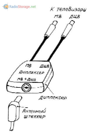
Rice. 5. Diplexer, which will frequency divide the signal into two outputs.
The described antenna has a one-way directionality, i.e. It only receives the TV signal from one side. If you need to receive a signal from two television centers (repeaters) located on opposite sides of your home, then you should buy a second antenna (of one or another design) and point it at the second television center.
Despite its popularity and good characteristics,The "Polish" antenna also has disadvantages:
- The most important of them is frequent damage to the antenna amplifier, or rather its field effect transistors. Reason - static electricity, lightning strike or power surges. Their harmful influence can be reduced by grounding the antenna.
- The fastening of the plastic holder of passive seven-element vibrators (directors) to the mounting box is weak, and often falls off due to the wind or the weight of birds, such as pigeons. You have to glue it.
- The same plastic director holders are bent due to the heating of the sun (Figure 6), and from solar radiation Cracks appear on them and the plastic falls apart. In this case, the characteristics of the antenna deteriorate, but the performance is maintained. A new holder with directors costs 2 UAH. 4. The upper vibrators, responsible for meter waves, are made of thin aluminum tubes and powerful wind or the weights of birds, such as pigeons, bend. At the same time, the antenna also deteriorates its characteristics, but remains operational.
Special mention should be made about modernized "Polish" antenna(Fig. 2). All the amplifiers, power supplies and matching boards described above are suitable for this antenna, but it also has its own peculiarities:
- All metal parts of the antenna have an anodized protective brass coating, which prevents corrosion.
- Active vibrators of the decimeter range are made of plates, so the radio characteristics of the antenna are better.
- The number of directors (passive vibrators) was reduced to three, which slightly worsened the antenna's directivity, but reduced the likelihood of their plastic holder being torn off.
All these “features” slightly increased the quality of this antenna, but the price increased by 50% (costs 55 UAH). Therefore, the price/quality ratio is not in favor of this antenna.

Rice. 6. Curvature of plastic director holders from the heating of the sun.
When selling their antennas, sellers provide them with a warranty of 1 to 6 months. The warranty applies to the entire antenna set, including the amplifier and power supply, however, warranty claims will not be accepted if:
- Damage to the amplifier board (mechanical damage, scratches, cracks, various inscriptions and stickers);
- Antenna disassembly;
- Coating boards with paint, varnish, wax, grease, glue, etc.;
- No production date on the document.
Polish antenna, like any technique, requires periodic Maintenance. At least once every two years it must be removed and the reliability of the contacts checked, the polyethylene bags that protect the amplifier from precipitation must be changed, and rust must be removed from its metal parts.
Unfortunately, while preparing this article, I could not get confirmation anywhere that “Polish” antennas are certified in Ukraine.
N. P. Vlasyuk, Kyiv.